Download this guide as a Word document
Introduction
This guide sheet is designed for public realm and highways professionals including modellers and technicians, decision makers, and interested campaigners and members of the public.
This sheet is more detailed and technical than many of our guides: Its main purpose is to support professionals in understanding the need for, commissioning and carrying out high-quality swept path analysis at complex locations on active travel routes.
Use our guide to defining accessible surface areas for active travel and public spaces to determine the accessible route or space area available to use for active travel and public space swept path analysis.
1 What is swept path analysis?
Swept path analysis is a way of working out whether a route is accessible to specific users. It involves computer modelling of a 2D vehicle on a plan drawing to see if the vehicle can move along the route without hitting anything.
For active travel (walking/wheeling and cycling), the most important vehicle for swept path analysis is the Cycle Design Vehicle (CDV). In this document, we also propose a smaller footway vehicle for situations where it is both impossible to provide space for the CDV on the footway and non-standard cycles are suitably provided for within another part of the highway. There must be suitable provision for the CDV on any highway to ensure Disabled people using cycles as mobility aids are able to access public spaces.
2 When is swept path analysis used?
Swept path analysis is used to design and assess areas of a route, such as junctions and crossing points.
On active travel routes, swept path analysis should be used to ensure that any unavoidable width restrictions, tight turn radii or other complex areas will be as accessible as possible to all legitimate route users. Swept path analysis is most likely to be needed where layouts of existing streets are being altered to provide better access for walking/wheeling and cycling.
Swept path analysis should always be used to develop best practice accessibility for active travel:
– Swept path analysis must never be used to justify creating unnecessary access restrictions for people walking/wheeling and cycling.
– Swept path analysis of motor vehicle provision should improve safety and accessibility by ensuring designs slow drivers as much as possible, for example by minimising carriageway widths and junction corner radii.
3 Swept path analyses for cycling and walking/wheeling[1]:
The Cycle Design Vehicle (CDV) should be modelled as a rigid quadricycle, not as an articulated cycle.
Modelling the CDV as a quadricycle is necessary to ensure spaces will work for people using larger rigid cycles such as side-by-side tandems, long recumbents and tandems (including recumbents and tandems with trailers, which are likely to be significantly longer than the CDV), and people using walking/wheeling and cycling infrastructure who are moving in accompanied groups.
We have sometimes seen the CDV modelled as an articulated vehicle comparable to a wide single cycle with child trailer attached. We do not believe this modelling adequately considers the movement and spatial needs of people riding larger cycle types and people in accompanied groups. Care must be taken to ensure modelling is not used to justify inaccessibility: Poorly thought through modelling is too often used to justify installation of access barriers with complex paths and severe width constraints that reduce movement on otherwise wide two-way paths to one-way only winding routes, unnecessarily introducing conflict and inaccessibility.
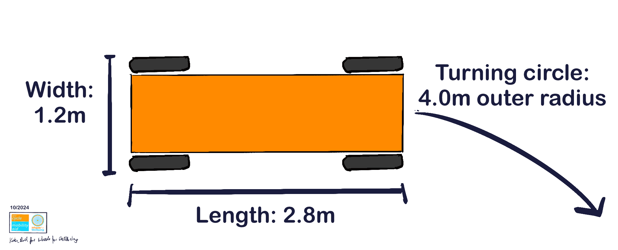
The Cycle Design Vehicle should be modelled as a rigid quadricycle with:
Width: 1.2m (LTN 1/20 5.4.1)
Length: 2.8m (LTN 1/20 5.4.1)
Turning circle: 4.0m outer radius (LTN 1/20 table 5-7) – Do not use radii in table 5-1 to model people moving along routes: These dimensions are for low-speed manoeuvres such as moving into parking spaces only and are likely to require riders of 2-wheeled larger cycles to slow to the point of losing stability).
3.1.1 The Cycle Design Vehicle for modelling:

4 Swept path analyses for walking/wheeling ONLY where cycling is not permitted AND where modelling using the Cycle Design Vehicle can be demonstrated to be impossible:
Use CDV dimensions above for modelling unless both:
- Achieving CDV minimum swept paths can be demonstrated to be impossible in the specific location under consideration AND
- Appropriate alternative safe, accessible options assessed to LTN 1/20 criteria exist to enable equally convenient access to the area for Disabled people using larger cycle types.
For example, it would be acceptable to assess a footway on an historic street using this minimum dimension vehicle, but only provided that there was adjacent cycling provision with a smooth sealed surface and meeting LTN 1/20 fig 4.1 criteria or better.
As far as we are aware, there is currently no designated footway vehicle for swept path analysis. Our suggestions here use the same principle as the Cycle Design Vehicle: This footway vehicle is a composite of legitimate footway users who are wider, longer and have greater turning circles than are usually anticipated for pedestrians by public realm designers.
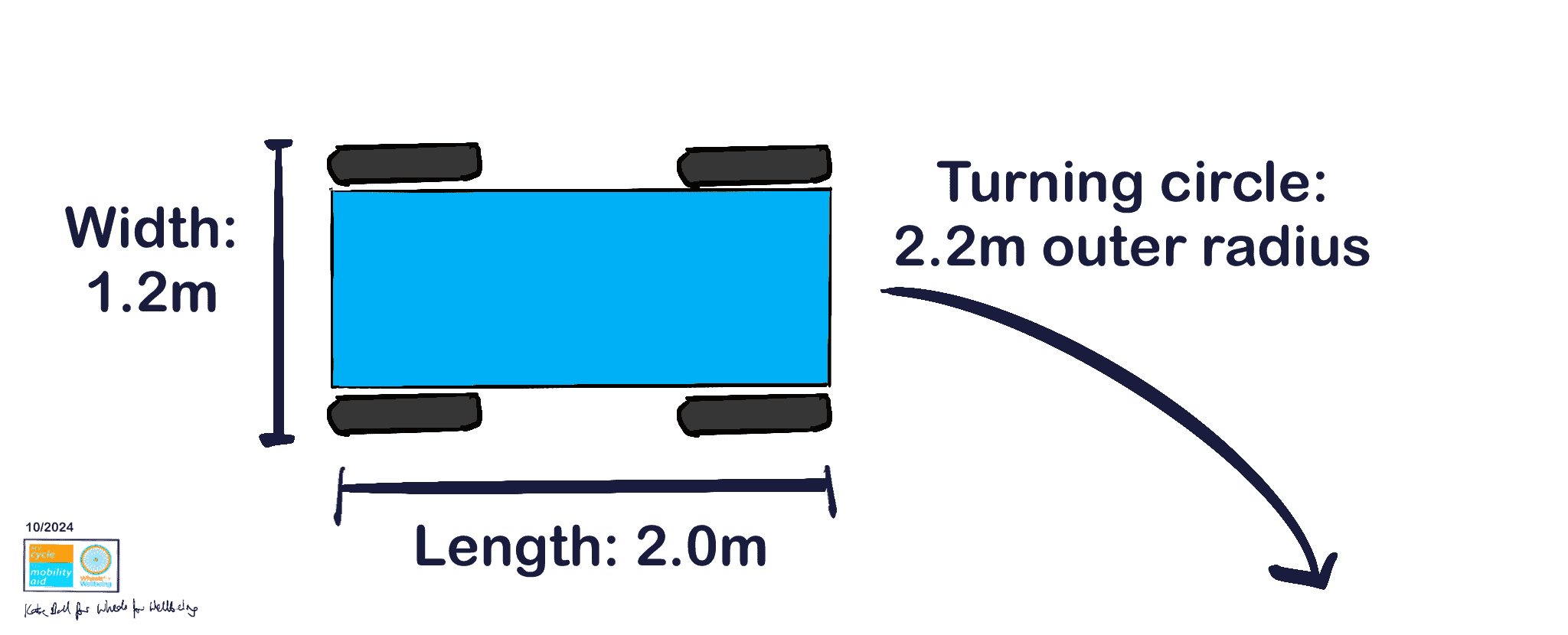
To model minimum required swept paths for pedestrians where achieving CDV requirements is demonstrably not possible, we recommend using a rigid body four-wheeled vehicle with:
Width: 1.2m (Inclusive Mobility (2021) 3.2, width of person being guided by another person)
Length: 2m (Inclusive Mobility (2021) 3.3, extrapolated length of extended leg wheelchair user plus assistant or recumbent handcycle, see also reference wheelchair research (2021) table 4.4 for occupied mobility scooter lengths)
Turning circle: 2.2m outer radius (Inclusive Mobility (2021) p25, electric pavement vehicle turning circle 4350mm)
4.1 Minimum swept path for walking/wheeling modelling – developing a minimum accessible footway vehicle:
This hypothetical vehicle is based on dimensions in the sources above and may be subject to future change. Many existing footways do not meet the requirements of access for this vehicle. While ultimately we hope that ways can be found to enable unimpeded access consistent with the CDV on all footways, this smaller swept path analysis vehicle is being proposed to inform changes to existing streetscapes, so that changes do not unduly introduce new restrictions to the mobility of Disabled people and other users of the pavement.
4.1.1 Proposed minimum dimensions for accessible footway vehicle

5 Factors which must be considered or excluded from surface dimensions for active travel swept path modelling:
Any routes too narrow for wider users to pass each other should have regular passing places appropriately sized for wider users.
Passing places should be spaced at whichever is the shorter of:
– Each within direct sight of the next, or
– Within 18m of each other (30 seconds’ travel for a Disabled user moving at 0.6m/s (walking/wheeling), extrapolated from Inclusive Mobility (2021) s11.3)
Use our guide to defining accessible surface areas for active travel and public spaces to determine the accessible route or space area to use in your swept path analysis.
Be aware that routes where Disabled/wheeling and non-disabled/walking users will have different desire lines are likely to introduce conflict points as users move in different directions and cross each others’ paths.
This situation typically occurs at complex or poorly-designed pedestrian crossings and locations such as transport hubs where steps and/or escalators and ramps and/or lifts are used by different groups.
Good practice is to design spaces such that all users move along the same routes as far as possible, without introducing conflict by restricting walking/wheeling and cycling desire lines.
[1] except for pedestrian-only spaces where meeting these criteria can be demonstrated to be impossible and there is other accessible provision meeting at least good practice LTN 1/20 (or Scotland Cycling By Design/ Wales Active Travel Act guidance) levels for cycling within the highway envelope.
